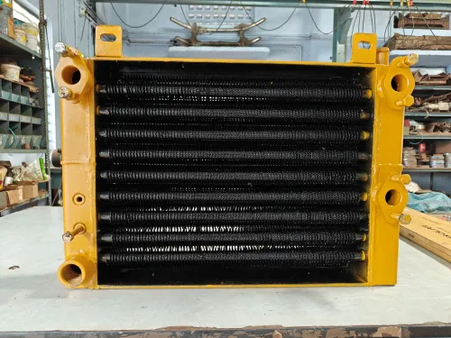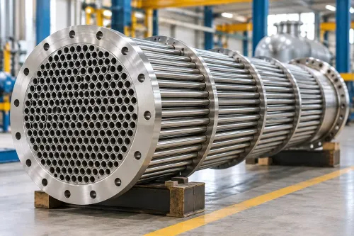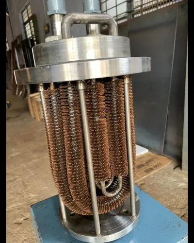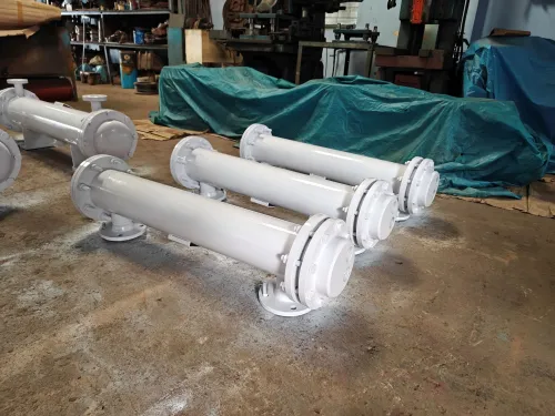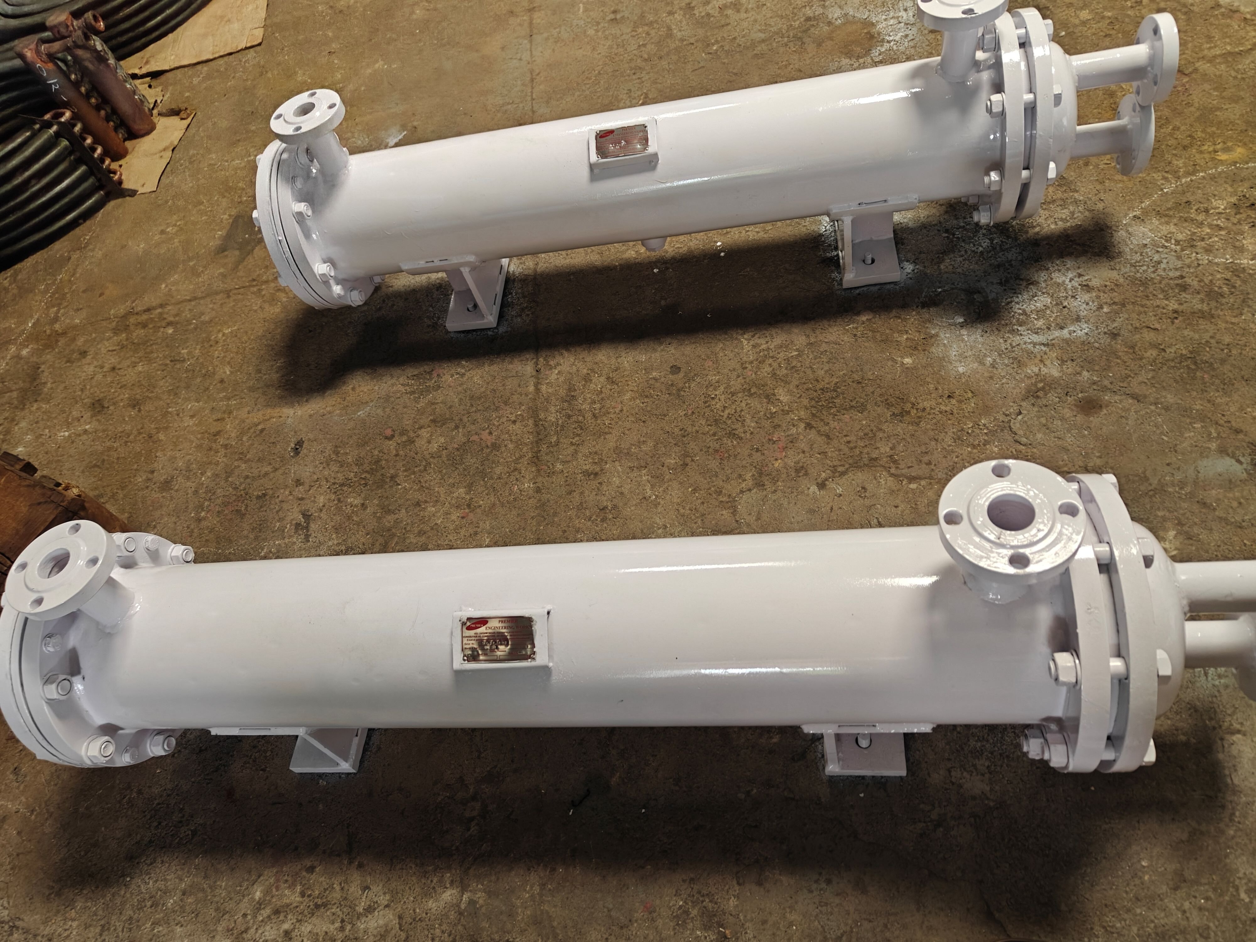
A condenser does more than move heat from one fluid to another: it removes vapour’s latent heat, controls condensing pressure, and returns usable liquid to the process. By the end, you will be able to verify the duty, identify the operating limits that control performance, and decide whether a shell-and-tube condenser fits your cooling system.
Key takeaways
- Calculate duty from mass flow, enthalpy change, and cooling-water temperature rise.
- Check fouling, flow velocity, pressure drop, and condensing temperature before comparing capacity.
- Compare tube-side and shell-side fluids, materials, cleaning access, and arrangement.
- Specify design duty, temperatures, pressures, fluids, materials, and allowable pressure drop.
What changes inside the condenser and the cooling cycle?
A shell and tube condenser removes heat as vapour changes into liquid. Vapour enters one side of the tube wall, commonly the shell side, and releases latent heat as it condenses; cooling water or another coolant flows through the tubes and carries that heat away.
The vapour side offers a large volume with low pressure drop, while tube-side water is easier to contain, clean, and protect through material selection.
In a refrigeration process cooling cycle, refrigerant leaves the compressor at compressor discharge as hot, high-pressure vapour. It condenses in the condenser, may be subcooled at the outlet, then passes through the expansion device, where pressure and temperature fall before the evaporator absorbs process heat and returns vapour to the compressor.
Cooling water follows its own circuit: supply water enters the tubes, gains heat, and leaves warmer.
A condenser is not merely a liquid-to-liquid shell-and-tube cooler: it performs a phase-change duty. An evaporator does the reverse on its process side, adding heat to a boiling fluid. Route vapour through the shell and water through tubes by convention, but consider the opposite arrangement for corrosive, high-pressure, fouling, or vacuum service.
- Provide a low-resistance condensate outlet and level control; trapped liquid can flood the bundle, cover heat-transfer surface, restrict vapour flow, and raise pressure drop.
- Specify subcooling only when the cycle needs liquid free of flash gas or a controlled liquid outlet temperature.
- Check drainage, outlet piping, and subcooling together; a simple low-point drain can leave liquid standing in the bundle.
- Treat condenser capacity, pressure drop, and stability as linked limits when liquid accumulation changes the available flow area.
How do you verify condenser duty before comparing capacity?
Begin with a condenser duty calculation based on the process enthalpy change, not on latent heat alone.
1. Calculate sensible heat: mass flow × specific heat × temperature change for any vapour cooling before condensation or liquid cooling after it.
2. Calculate latent heat: vapour mass flow × latent heat at the operating pressure. Add desuperheating, condensate subcooling, heat leaks, and non-condensable-gas cooling where they apply.
3. Add those loads to obtain total process duty. Latent heat alone can understate surface area because the omitted sensible loads still require a temperature difference and heat-transfer surface.
4. Calculate cooling-water duty independently: water flow × specific heat × water temperature rise. Compare this result with the process-side duty after allowing for heat loss and measurement uncertainty.
5. Compare the calculated duty with the stated 4700 kW nameplate limit. Treat that figure as a rating at defined flow rates, inlet temperatures, condensing pressure, fouling resistance, pressure drops, and fluid properties—not as a universal guarantee. Confirm those boundary conditions before accepting the comparison.
6. Check the condensing temperature against the cooling-water inlet temperature and the specified approach temperature. Pressure drop changes the local saturation condition along the condenser, while water flow and temperature rise affect the available driving force.
Adding area cannot overcome an unfavorable water temperature or approach; the required condensing temperature depends on all four factors, not area alone.
Which operating details determine real heat-transfer performance?
Real performance is set by pressure, temperatures, flow, cleanliness, and drainage—not nameplate area alone. Connect the duty calculation to allowable shell- and tube-side pressure drops, design pressure, temperature limits, and the cooling-water inlet temperature.
Shell-side pressure drop changes vapour pressure and therefore saturation temperature along the exchanger. Using one constant condensing temperature can overstate LMTD; calculate the local temperature profile, then apply the LMTD correction factor required for the selected multipass arrangement.
| Operating detail | Performance gain | Cost or failure risk |
|---|---|---|
| Higher water velocity | Higher tube-side coefficient and less deposition | More pump power, pressure drop, erosion, vibration, and tube-wall wear |
| Fouling allowance | Extra thermal resistance in the design margin | Reduced heat transfer, narrower passages, higher pressure drop, and under-deposit corrosion |
| Adequate condensate outlet | Stable drainage and heat-transfer surface | Flooding, rising liquid level, and loss of condensing area |
Choose velocity against tube material, water chemistry, suspended solids, erosion limits, and allowable pressure drop—not coefficient alone. Treat fouling allowance as added thermal resistance and hydraulic restriction, not a cleaning plan; specify the contaminant, performance-degradation limit, cleaning method, and access.
Air, nitrogen, and hydrogen create a diffusion barrier at the condensing surface, reducing local heat transfer and raising required pressure. Provide high-point vents, purge connections, or dedicated air removal.
Size the condensate outlet for peak flow, control level to prevent bundle flooding, and include subcooling only where its duty and drainage support it. In vacuum service, external-pressure buckling can govern shell and tubesheet design even when internal pressure is low.
What should you compare before choosing the condenser arrangement?
Compare each arrangement against lifetime utility and site constraints, not heat-transfer area alone.
| Arrangement | Water consumption | Power, ambient dependence, and site effects | Access and maintenance |
|---|---|---|---|
| Cooling-water condenser | Continuous water use; chemistry control is essential | Pumping power; low dependence on outdoor air temperature; compact; quiet; no visible plume | Tube cleaning is direct, but water treatment, inspection, and fouling control add burden |
| Air-cooled condenser | No process cooling-water use | Fan power; performance falls as ambient temperature rises; large footprint; fan noise; no water plume | Coil cleaning is accessible, but many fans, motors, and fin blockage increase maintenance |
| Evaporative condenser | Lower water use than once-through cooling, but requires makeup and blowdown | Fan and water-pump power; strong ambient dependence; compact; fan noise; plume risk in cold or humid weather | Scale and biological control complicate cleaning and maintenance |
| Hybrid condenser | Reduced water use with air-side backup or trim cooling | Fan and pump power; improved seasonal flexibility; larger controls package; moderate noise and plume risk | Two heat-rejection systems mean more valves, instruments, and maintenance points |
A cooling-water condenser is attractive where a reliable treated-water circuit, compact footprint, and quiet operation matter. Poor chemistry control can make scaling, pitting, under-deposit corrosion, or erosion-corrosion unacceptable; chloride, oxygen, deposits, velocity, and temperature determine tube life.
If no vapour must condense, compare a liquid-to-liquid cooler or another heat exchanger instead. Severe vibration, highly corrosive fluids requiring different construction, very limited plot space, or unstable cooling-water quality calls for engineering review—not an automatic condenser purchase.
What information belongs in a condenser purchase specification?
A comparable quote starts with complete condenser sizing data, not a heat-load figure alone. Give every vendor the same process, utility, mechanical, and operating information so differences in area, materials, pressure drop, and price reflect real design choices.
1. State the process-fluid name and composition, vapour fraction, mass or volumetric flow, inlet and outlet temperatures, operating and design pressures, vacuum cases, allowable shell-side and tube-side pressure drops, and required turndown.
2. Define the cooling-water service: inlet temperature, flow, cooling-water chemistry, chloride level, suspended solids, and seasonal temperature range. Name the fouling contaminant, cleaning method, compatible materials, and tube-material limits for corrosion, erosion, and deposits.
3. Specify installation orientation, nozzle locations, high-point venting, low-point drainage, condensate outlet sizing, level control, subcooling needs, and piping constraints. Include the required TEMA construction class and applicable pressure-vessel code, such as ASME Section VIII, Division 1, instead of requesting a generic standard exchanger.
4. Require the vendor to state the heat-transfer area basis, fouling resistance, condensing pressure profile, LMTD correction factor, tube velocity, plugged-tube assumption, vibration review, and performance guarantees. Ask how the design behaves at minimum flow and seasonal cooling-water temperatures.
Premier Engineering Works can use this duty and utility data in an application review, testing whether custom equipment fits the actual service rather than inferring suitability from a 4700 kW figure alone.
Related products
 | Cooling Equipment Our condensers boast impressive capacities, reaching up to a remarkable 4700 kW. View product → |
 | Shell and Tube Condenser Shell and Tube Condenser Manufacturer In Coimbatore | Premier Engineering Works View product → |
Frequently asked questions
What changes inside a shell and tube condenser and the cooling cycle?
Process vapour releases latent heat as it condenses on one side of the tube wall. Cooling water or another coolant absorbs that heat through the tubes, warms up, and returns to the cooling circuit.
How do you verify condenser duty before comparing capacity?
Calculate duty from the vapour mass flow and enthalpy change, then cross-check it against coolant flow multiplied by coolant specific heat and temperature rise. Include sensible cooling or superheat removal when the inlet vapour is not saturated.
Which operating details determine real heat-transfer performance?
Condensing temperature, coolant inlet temperature, flow velocity, fouling resistance, non-condensable gases, pressure drop, and the cleanliness of both fluid paths determine actual performance.
What information belongs in a condenser purchase specification?
State the duty, process and coolant fluids, flow rates, inlet and outlet temperatures, operating and design pressures, allowable pressure drops, materials, corrosion conditions, fouling allowance, tube layout, cleaning access, and inspection requirements.