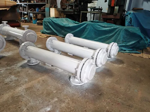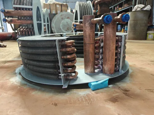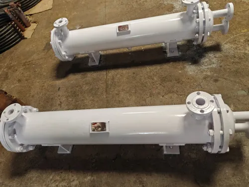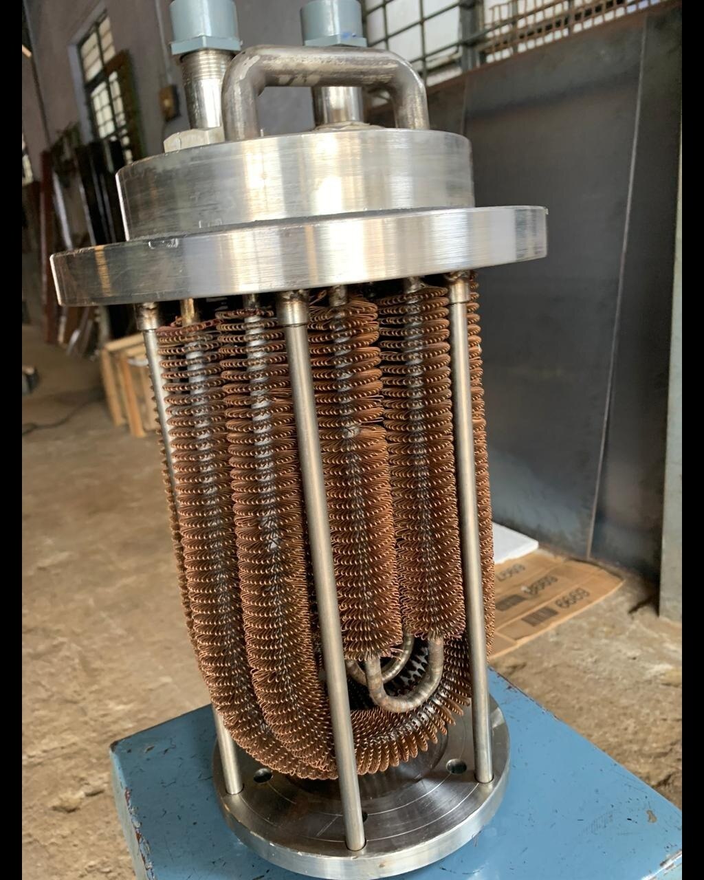
High-temperature service subjects heat exchangers to differential expansion, thermal cycling, pressure, corrosion and vibration at the same time. You will be able to judge whether a U-tube bundle fits your process by comparing its expansion behaviour, material limits, operating conditions, maintenance demands and design requirements.
Key takeaways
- Use U-tubes to absorb differential expansion without a sliding expansion joint.
- Set temperature and pressure limits for the complete exchanger, not the tubes alone.
- Choose floating-head construction when tube-side cleaning or inspection controls the design.
- Specify bend radius, vibration checks, materials and service access before ordering.
How a U-Tube Bundle Handles Differential Expansion
A U-tube heat exchanger bundle has both ends of every tube fixed into a single tubesheet. Each tube bends through 180 degrees at its far end, creating an out-and-back, normally two-pass tube-side path with inlet and outlet on the same end.
That U-bend accommodates differential thermal expansion through flexure. For example, a 10 m austenitic stainless steel tube with an expansion coefficient of about 17 × 10^-6/K changes length by approximately 51 mm over a 300 K rise: 10 × 17 × 10^-6 × 300 = 0.051 m.
The bend absorbs most of that axial growth instead of forcing the tube and shell to expand against one another.
| Construction | Expansion behaviour | High-temperature trade-off |
|---|---|---|
| U-tube bundle | U-bend flexes to absorb tube-versus-shell growth | Less restraint, but curved tubes are harder to inspect and mechanically clean |
| Fixed-tubesheet exchanger | Straight tubes remain restrained at both ends | Large temperature differences can create high axial stress or require a shell expansion joint |
| Floating-head exchanger | One end moves relative to the shell | Good expansion accommodation and tube access, with more seals and maintenance complexity |
The U-bend reduces restraint compared with a fixed straight-tube arrangement; it does not eliminate bend stress. Thermal gradients between the tube legs, support restraint, tubesheet loads, bend ovality and repeated start-up cycles can produce thermal-fatigue damage. Tube-to-tubesheet joints also remain potential leak points.
Temperature and Pressure Limits Depend on the Entire Design
A U-tube bundle has no universal maximum temperature, pressure range, or allowable temperature difference. Suitability comes from the complete design: tube, shell, tubesheet, weld and gasket materials; pressure-vessel code allowable stresses; corrosion allowance; creep resistance; and the temperature-dependent properties of both fluids.
Operating temperature describes normal service. Design temperature is the value used for mechanical sizing and must cover credible transients, not just the steady-state reading.
| Parameter | Operating basis | Design basis |
|---|---|---|
| Temperature | Normal shell-side and tube-side temperatures | Maximum credible temperature on each side |
| Pressure | Normal pressure on each side | Design pressure on each side, including upset conditions |
| Pressure drop | Allowable loss during operation | Limit used to size passages, flow rate and pumping capacity |
| Temperature difference | Routine shell-to-tube difference | Maximum allowable temperature difference during an upset |
Specify these inputs for both sides:
- Heat duty, flow rate and fluid composition
- Design temperature and operating temperature
- Design pressure and pressure drop
- Start-up and shutdown temperatures
- Ramp rates and maximum shell-to-tube temperature difference during an upset
- Fouling tendency and planned cleaning interval
Fluid composition determines corrosion, oxidation and gasket compatibility; flow rate affects heat transfer, erosion and vibration. Fouling reduces heat-transfer performance and narrows flow passages, while repeated thermal cycling creates fatigue at the U-bend, supports and tube-to-tubesheet joints.
A rapid start-up can produce a damaging temperature gradient even when the final operating temperature is within the material rating, so transient conditions can govern the mechanical design.
U-Tube, Fixed-Tubesheet or Floating-Head: Which Fits High Temperature?
For a large shell-to-tube temperature difference, a U-tube bundle is usually the least expansion-restrained choice. Both tube ends terminate at one tubesheet, so the bundle forms a two-pass tube circuit: fluid travels down one leg, turns through the 180-degree bend, and returns through the other.
| Option | Expansion behaviour | High-temperature trade-off |
|---|---|---|
| U-tube bundle | The U-bend flexes as the tubes grow, normally without a shell expansion joint. | Handles large temperature differences and severe startup or shutdown transients, but the bend is harder to inspect and mechanically clean. |
| Fixed-tubesheet heat exchanger | Straight tubes are restrained at both ends with the shell, so differential growth creates axial stress. | A large temperature difference can require a shell expansion joint; otherwise tubes, tubesheets or shell experience high thermal loads. |
| Floating-head heat exchanger | The floating head allows the tube bundle and shell to expand independently. | Offers easier tube-side access, but adds sealing surfaces, fabrication work, inspection points and maintenance complexity. |
A U-tube also has fewer tube-to-tubesheet joints than a two-tubesheet arrangement, reducing one major leak boundary without eliminating leakage risk. Its cost is service access: rigid cleaning rods cannot pass around the bend, and curved sections complicate nondestructive inspection.
Choose the U-tube when expansion restraint and transient stress dominate; choose a floating head when frequent tube-side cleaning or inspection matters more. A fixed-tubesheet design fits high-temperature service when the temperature difference is controlled, or when a properly designed shell expansion joint manages the movement.
Build the Selection Specification Before Choosing Materials
Approve the bundle only after fixing the heat duty and every condition that governs expansion, pressure and fouling. Use this checklist:
- Shell-side and tube-side design temperature
- Shell-side and tube-side design pressure
- Allowable pressure drop on each side
- Flow rate, fluid composition and fouling tendency
- Tube diameter and tube pitch
- U-bend radius and forming method
- Tube support spacing, including the bend region
- Tubesheet thickness and corrosion allowance
Choose the tube material against the actual chemistry and temperature, not the U-bend shape.
| Material | Suitable service | Main concern |
|---|---|---|
| Carbon steel | Lower-temperature, non-corrosive duty | Loses margin as temperature, corrosion or cycling increases |
| 304 or 316 austenitic stainless steel | Corrosive service where stainless temperature capability is adequate | Chlorides, creep and thermal cycling can exceed its limits |
| Nickel or other high-temperature alloys | Chloride attack, reducing or oxidising chemistry, creep, oxidation or severe cycling | Higher cost and more demanding fabrication |
U-bend geometry accommodates differential expansion; it does not replace high-temperature materials or eliminate thermal stress. Specify tube thinning, bend ovality, wrinkling and residual-stress limits, then verify them by qualified inspection.
The design review must also cover tube-to-tubesheet attachment, gasket rating at design temperature and pressure, weld integrity, pressure-vessel code compliance, support wear, vibration and fatigue. A tube that survives expansion can still fail from creep, corrosion or a leaking gasket.
Verify Bend Integrity, Vibration and Service Access
A suitable thermal calculation is only permission to examine the bundle mechanically. Thermal-expansion tolerance is not resistance to elevated temperature: the U-bend does not stop oxidation, corrosion, creep, vibration, gasket failure or thermal-fatigue cracking. Repeated cycling, temperature stratification and ramp rate can concentrate alternating stress in the bend and tube-to-tubesheet joints.
Check the following before approving the design:
- Inspect the 180-degree bend for flattening, wall thinning, wrinkling and cracks using qualified nondestructive examination, including eddy-current testing where suitable.
- Assess flow-induced vibration, support spacing and rubbing clearance; overly tight supports restrict thermal flexure, while loose supports permit wear.
- Include mechanical and fatigue assessment for start-up, shutdown, upset mixing and repeated temperature cycles.
- Confirm gasket ratings, tube-to-tubesheet integrity, material ratings and pressure-vessel code calculations.
| Inspection target | Check | Failure risk |
|---|---|---|
| U-bend | Probe access and signal interpretation | Missed cracking or thinning |
| Tube supports | Contact pressure, clearance and wear | Fretting and vibration damage |
| Bundle route | Pull space, lifting points and clearances | Replacement blocked by plant layout |
The curved geometry complicates internal probe access and signal interpretation, so a visual check from the tube ends is not enough. Rigid cleaning rods and rotary tools cannot pass through the bend; water lancing, flexible tools, chemical cleaning or tube replacement may be required. Design individual tube plugging into the maintenance plan.
Premier Engineering Works can translate process data into a custom bundle specification while keeping code calculations, material ratings and service access central to the selection.
Frequently asked questions
How does a U-tube bundle handle differential expansion?
Each tube is fixed at one tubesheet and bends through 180 degrees, allowing the two tube legs to expand relative to the shell without imposing the same axial restraint as a fixed-tubesheet exchanger.
What determines a U-tube heat exchanger’s temperature and pressure limits?
The complete design sets the limits, including tube and shell materials, tubesheet thickness, welds, gaskets, tube-to-tubesheet joints, thermal gradients and the governing pressure-vessel code.
When is a U-tube exchanger better than a fixed-tubesheet or floating-head design?
A U-tube suits high-temperature service when differential expansion is the main concern and tube-side cleaning is manageable; fixed tubesheets suit simpler, cleaner services, while floating heads suit applications requiring stronger tube-side access.
What should you specify before selecting materials for a U-tube bundle?
Define process fluids, design temperature and pressure, corrosion risks, flow rates, fouling tendency, cleaning method, metallurgy, tube dimensions, code requirements and allowable pressure drop.
How do you verify U-tube bend integrity and service access?
Review the bend radius and wall thinning, inspect for cracks and ovality, assess flow-induced vibration, and confirm that the bundle can be removed, inspected and cleaned with the planned equipment.