A turbocharger can deliver compressed air to an engine, but that air leaves the compressor hot and less dense. By the end, you will be able to trace the cooling circuit, compare cooler arrangements, specify the operating data that matters, and check whether a proposed unit will protect performance under real sea conditions.
Key takeaways
- Cool compressed air to preserve oxygen supply, rated power and safe combustion temperatures.
- Trace both charge-air and cooling-water paths before diagnosing poor engine performance.
- Size the cooler from airflow, temperatures, pressure drop, fouling and seawater conditions.
- Verify materials, pressure tests, connections and service access before purchase.
Why cooling compressed air protects engine power and reliability
A marine charge air cooler removes heat from compressed intake air after the turbocharger compressor and before the intake manifold. Cooler air is denser, so more oxygen enters each cylinder at the same volume. The engine can then maintain its intended air-fuel ratio and produce rated power without excessive combustion heat.
Pressure drop is as important as cooling capacity. Excessive air-side pressure loss forces the turbocharger to work harder and reduces the pressure available to the cylinders. Excessive water-side pressure loss restricts coolant flow, allowing charge-air temperature to rise and reducing the engine’s power margin.
If the cooler cannot hold its specified outlet temperature at high load, exhaust-gas temperature and smoke can rise. Continued operation in that condition increases thermal stress and can trigger a load limitation when the vessel needs propulsion power most.
A low-temperature freshwater circuit commonly carries heat from the charge-air cooler to a central cooler, while seawater remains on the central cooler’s opposite side. This arrangement protects engine-side equipment from direct seawater exposure and gives tighter control of charge-air temperature.
Cooling also affects combustion and NOx, so changing water-control settings or bypass operation requires checking the engine’s certified settings and MARPOL Annex VI compliance; it is not a substitute for an emissions-control system.
Follow the air and water through the cooling system
After the turbocharger compresses intake air, the air temperature rises and its density falls. The charge-air cooler removes that heat before the air reaches the intake manifold, using either water or outside air as the heat sink.
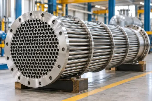
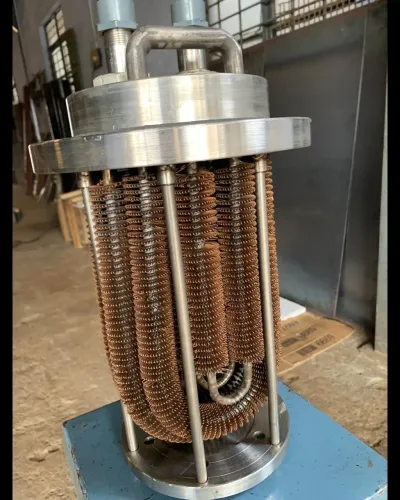
In an air-to-water charge air cooler, compressed air passes through narrow tubes or passages while cooling water flows across them. On a vessel with central cooling, a freshwater cooling circuit carries heat from the cooler to a central freshwater cooler; a separate seawater cooling circuit removes that heat overboard.
Seawater therefore stays away from the engine-side cooler, reducing corrosion and giving tighter temperature control.
The flow is straightforward: turbocharger compressor, charge-air pipe, cooler, then intake manifold and cylinders. On the water side, the low-temperature freshwater circuit enters the cooler, absorbs heat, and leaves at a higher temperature.
A three-way valve or bypass can restrict cooling during cold-water, low-load operation so the outlet air does not fall below its dew point.
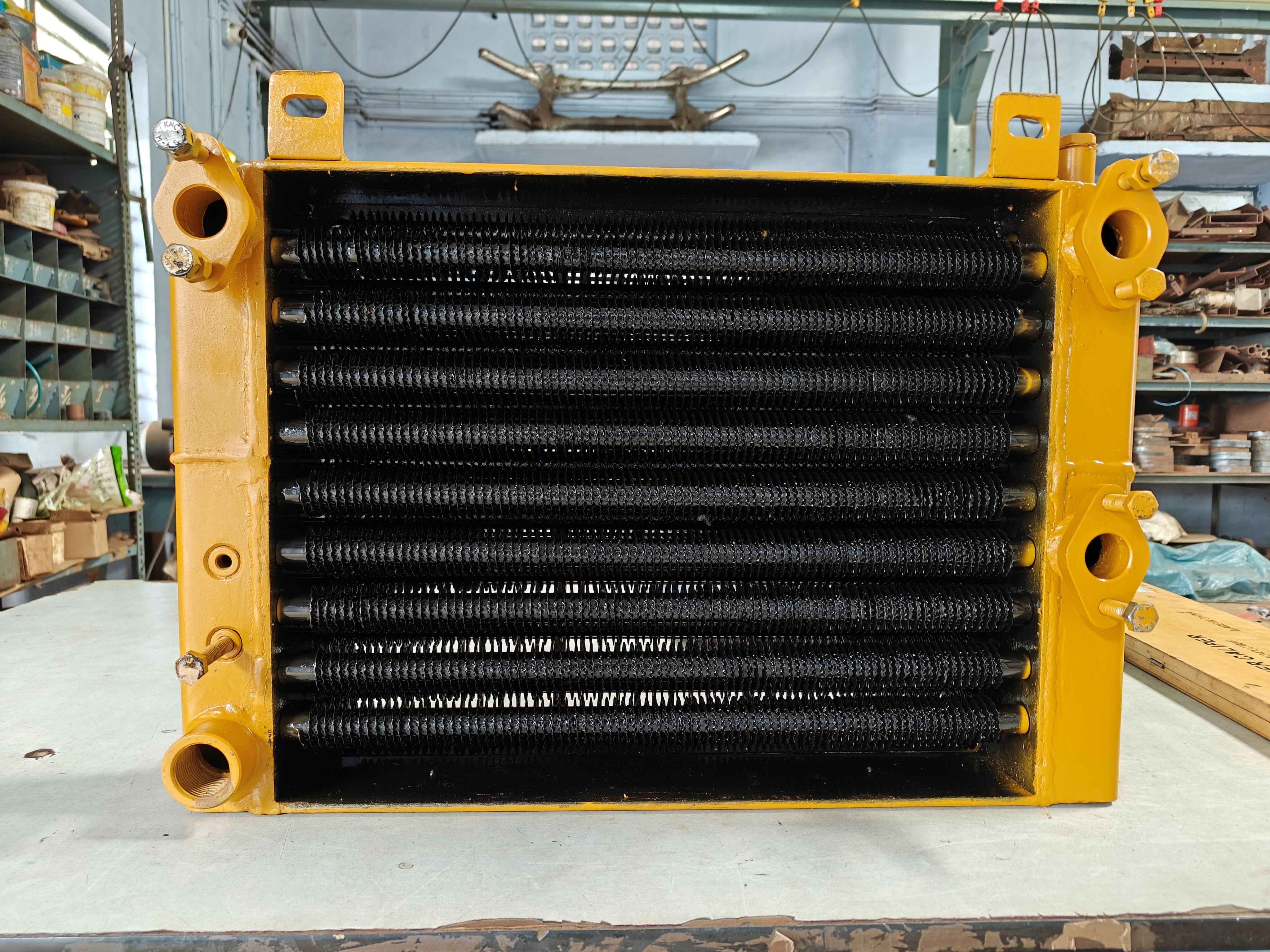
An air-to-air charge air cooler sends compressed air through a finned radiator exposed to outside air. It suits smaller or high-speed vessels with short intake routes, adequate ventilation, and space for a large cooler and ducting.
| Air-to-air charge air cooler | Uses outside air | Simpler water arrangement, but exposed to salt, dust, and restricted airflow |
|---|---|---|
| Air-to-water charge air cooler | Uses a closed water loop | Compact engine-room installations and centrally cooled vessels |
Air-to-water designs add pumps, valves, and water-side fouling points; air-to-air designs depend more heavily on clean fins and unobstructed ventilation. Both need pressure-drop and temperature monitoring, not heat-transfer capacity alone.
Choose the cooler from boundary conditions, not catalogue capacity alone
A cooler sized for its rated heat duty at one set of conditions may fail at sea if those conditions do not match the engine’s load and cooling circuit.
Select it at maximum continuous rating, using the charge-air mass flow, compressor outlet temperature, design cooling-water flow, inlet-water temperature, allowable air-side and water-side pressure drops, and stated fouling allowance.
Give the supplier these design inputs:
- Engine charge-air mass flow and pressure at maximum continuous rating
- Compressor outlet temperature and target intake temperature
- Cooling-water flow, inlet temperature, salinity, and available pressure
- Maximum permitted air-side and water-side pressure loss
- Fouling allowance, cleaning method, material limits, and required service life
The target intake temperature is not the lowest outlet temperature the cooler can produce. It is the engine maker’s specified temperature, reached without excessive pressure loss or condensation. Include tropical seawater conditions in the thermal margin; a cooler that passes in cold water can lose capacity when seawater is hot.
| Design condition | Selection consequence | Detail to verify |
|---|---|---|
| Cold seawater or low engine load | Risk of overcooling and condensation | Three-way valve, bypass, or low-temperature circuit control maintaining a minimum charge-air temperature |
| Hot seawater at maximum rating | Reduced temperature driving force | Rated heat duty and target intake temperature demonstrated at the specified water inlet temperature |
| Fouled seawater passages | Higher pressure drop and uneven cooling | Tube or plate arrangement, corrosion-resistant materials, cleaning access, and fouling allowance |
Do not accept catalogue capacity without its air flow, temperature difference, water flow, and pressure-drop conditions. Corss-check those figures on the same basis.
Compare designs and verify the cooler before purchase
Do not compare coolers by kilowatts alone. Request a performance sheet showing air mass flow, compressor discharge temperature, cooling-water flow, inlet-water temperature, outlet-air temperature, allowable pressure drop, fouling allowance, and the design seawater temperature at maximum continuous rating.
| Evidence to compare | What it proves | Failure if missing |
|---|---|---|
| Thermal test or calculation | The stated duty applies to your operating conditions | Catalogue capacity misleads |
| Air- and water-side pressure-drop data | The turbocharger and pump will not face excessive resistance | Lost boost or cooling flow |
| Design pressure and pressure-test record | The shell, headers, tubes, and joints withstand service pressure | Leakage or rupture |
| Tube construction and material schedule | The chosen tubes resist corrosion and galvanic attack | Early seawater failure |
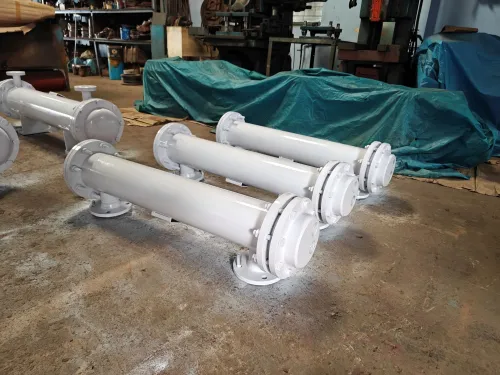
Ask for a dimensional drawing, connection schedule, mounting details, removable-core clearance, dry weight, and maintenance access. A supplier such as Premier Engineering Works should use those documents to check the proposed cooler against the engine installation rather than select a nominal capacity.
Confirm the fit against the engine maker’s charge-air drawing and piping isometric. Check these points before issuing a purchase order:
- Charge-air inlet and outlet sizes, flange standard, centreline height, and flow direction
- Cooler envelope, lifting points, supports, vibration limits, and tube-bundle removal path
- Cooling-water inlet and outlet sizes, flow requirement, valve arrangement, drains, and vents
- Engine air-flow demand and maximum permitted charge-air temperature and pressure drop
- Remaining cooling capacity after one train, pump, strainer, or valve is unavailable
A cooler that fits the pipe but blocks service access is not a confirmed fit. Get the final interface drawing approved by the engine maker and shipyard.
Related product
 | Marine Equipment Cooling Premier Engineering Works specialises in the design and manufacturing of marine heat exchangers that are engineered to withstand the harsh conditions... View product → |
Keep cooling performance stable during service at sea
A rising charge-air temperature trend at the same engine load signals reduced heat transfer before power loss appears. Compare cooler inlet and outlet temperatures, cooling-water temperatures, water-side differential pressure, air-side differential pressure where fitted, and exhaust temperatures against the clean-cooler baseline.
1. Log readings at steady loads and similar seawater temperatures. A rising temperature approach, increasing water-side differential pressure, or increasing air-side pressure drop points to fouling, blocked passages, or poor flow distribution. Inspect strainers, drains, and cooler surfaces before the engine reaches its temperature or exhaust limit.
2. Check for air-side condensation after cold-water or low-load operation. Water at the charge-air outlet, a wet drain, or corrosion in downstream piping indicates that the air temperature is approaching its dew point. Confirm the minimum outlet-temperature setting and adjust the three-way valve or bypass; do not solve recurring condensation by ignoring the drain.
3. Test overcooling protection during cold seawater conditions and low load. A control valve stuck open can drive outlet temperature below the engine maker’s specified minimum, destabilise combustion, and increase corrosion risk. Verify valve travel, temperature-sensor agreement, alarms, and the control system’s response to a failed sensor.
4. Prove the response to one failure at a time: stop a cooling-water pump, isolate a sensor, remove control power, and simulate a high-temperature alarm under the approved procedure. Confirm that the remaining equipment gives an alarm, holds a safe temperature, and permits load reduction before engine limitation.
Treat changes to cooling temperature or bypass settings as engine-setting changes. Check their effect on certified combustion settings and MARPOL Annex VI emissions compliance.
Frequently asked questions
Why does a marine charge air cooler protect engine power and reliability?
It reduces compressed-air temperature, increasing air density so each cylinder receives enough oxygen for the intended air-fuel ratio and rated power. Lower intake temperature also limits excessive combustion heat.
How does air and water move through a marine charge air cooler?
Turbocharger-compressed air flows through the cooler core before reaching the intake manifold. A separate cooling-water circuit removes heat, using seawater or a freshwater loop depending on the engine installation.
What information is needed to choose the right marine charge air cooler?
Use engine airflow, compressor outlet temperature, target charge-air temperature, allowable pressure drop, cooling-water temperature and flow, seawater quality, design pressure and available space.
How can you verify and maintain a marine charge air cooler?
Compare core design, materials, connections, pressure-test records and service access before purchase. During service, inspect for fouling, leaks, corrosion, blocked passages and rising air-side pressure drop.