A lubrication system needs a cooler when its heat balance cannot keep oil below the supplier’s maximum supply temperature at the machine’s worst operating condition. By the end, you will be able to estimate the cooling duty, set a safe oil outlet temperature, compare exchanger types, and write a specification that accounts for fouling, pressure drop, leaks and maintenance.
Key takeaways
- Compare peak oil temperature with the lubricant supplier’s maximum limit.
- Calculate heat load from oil flow, heat capacity and allowable temperature rise.
- Match exchanger flow arrangement to oil viscosity, pressure and cooling-water conditions.
- Specify fouling allowance, leak consequences, materials and test requirements.
Identify the heat sources before deciding that you need a cooler
A shell-and-tube oil cooler is necessary when oil temperature exceeds the lubricant supplier’s maximum operating limit at the worst combination of machine load, ambient temperature, cooling-water temperature and fouling. A rising temperature during continuous duty is also a warning: the system’s heat balance is failing, even if the oil remains within range for short runs.
Identify the heat entering the circuit before blaming the cooler:
- Measure bearing friction heat in bearings, thrust bearings and seals. A temperature rise at constant speed and load points to mechanical losses.
- Check gear meshing and gearbox churning. High-speed gears can transfer substantial heat into recirculated oil.
- Examine hydraulic throttling, compressor loading and turbine operation. Pressure losses and fluid work become heat in the lubricant.
- Include heat conducted from a hot machine casing, nearby steam lines or a high-temperature process.
- Record oil flow, inlet temperature and outlet temperature during the heaviest continuous operating period. Oil recirculation through a high-power system can keep adding heat even when individual components appear normal.
Do not size the cooler from motor or shaft power alone; those figures do not reveal how much power becomes lubricant heat. Use the oil supplier’s lubricant operating range, then set a target outlet temperature that preserves viscosity and avoids water condensation.
A bypass or three-way temperature-control valve lets oil warm after cold start instead of forcing every litre through the cooler.
For petroleum or petrochemical service, check the governing editions of API 614, API 660 and applicable TEMA requirements before accepting a generic design.
Calculate cooling duty and set the oil outlet temperature
Start with the oil, not the motor nameplate. Calculate heat removal from the actual oil mass flow and the permitted temperature drop: Q = m × Cp × ΔT. With oil flow in kg/s, specific heat in kJ/kg·K, and ΔT in K, the result is kW.
Use operating data from the worst design case:
- Oil mass flow at the minimum expected flow, not the pump’s rated capacity.
- Oil inlet temperature at the hottest machine condition.
- Target outlet temperature based on the oil supplier’s recommended operating range.
The target outlet temperature must keep the lubricant cool enough for bearings, gears, seals and hydraulic components without making it too viscous. Excessive cooling raises pressure drop, restricts flow during start-up and can create water condensation when cold surfaces fall below the surrounding air’s dew point.
Compare the calculated oil heat removal with heat entering the circuit from bearings, gear meshing, hydraulic throttling, compressor or turbine operation, casing heat gain and recirculation. Motor or shaft power alone cannot provide that balance: only part of its energy becomes oil heat, while auxiliary components can add substantial load.
Evaluate the duty at the hottest cooling-water temperature available in the design season and include fouling allowance. A very small oil-to-water temperature approach makes capacity sensitive to fouling and seasonal changes; extra area or a higher target outlet temperature can produce a more stable result.
Record maximum start-up viscosity, minimum oil temperature, allowable oil-side pressure drop and the bypass or relief path. A modest normal duty still demands a shell diameter that passes cold, thick oil safely.
Choose the exchanger type and flow arrangement that fits the service
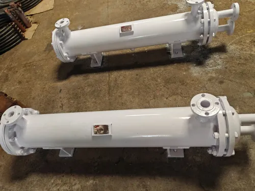
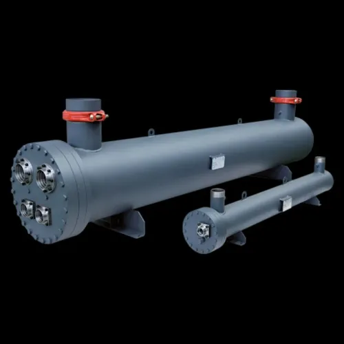
Choose a shell-and-tube oil cooler when the lubrication circuit has high design pressure, viscous oil, severe temperature cycling, dirty service, or a need for mechanical tube cleaning. A plate heat exchanger is more compact and transfers heat efficiently, but gasket temperature or chemical limits and narrow passages can become failure points.
| Option | Main advantage | Choose it when |
|---|---|---|
| Shell-and-tube oil cooler | Robust construction and cleanable tubes | Pressure, fouling, cycling, or leak consequences rule out gasketed plates |
| Plate heat exchanger | Compact size and high heat-transfer coefficient | Clean fluids, moderate pressure, compatible gasket temperatures, and easy access for gasket replacement |
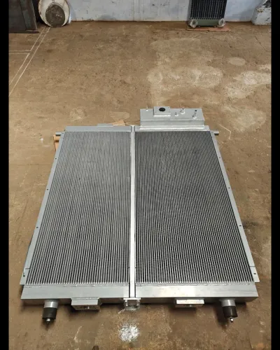
| Air-oil cooler | No cooling-water circuit | Water is unavailable, unreliable, corrosive, or unacceptable as a contamination source |
| Jacketed tank | Heats or cools a vessel wall | Oil is held in a tank or batch vessel; it is a poor substitute for continuous high-duty circulation |
Use countercurrent flow when the design allows it: it gives a smaller temperature approach than parallel flow for the same area. Add tube or shell passes only after checking oil-side pressure drop, tube-wall temperature, thermal expansion, viscosity at startup, and the result of a cross-fluid leak.
More passes increase velocity and heat transfer but also raise pressure loss.
For continuous-duty lubrication, specify two 100%-capacity coolers with isolation and changeover valves when a shutdown is unacceptable. For petroleum or petrochemical service, identify the governing editions of API 614, API 660, and TEMA before accepting a generic design.
Check pressure, viscosity, fouling and leak consequences before specifying the cooler
A thermally adequate cooler can still starve a remote bearing if its oil-side pressure drop consumes the available pressure. Specify maximum start-up viscosity, minimum oil temperature, allowable pressure drop, and the bypass or pressure-relief arrangement for cold start; a high-viscosity start can require a larger shell or wider passages.
- Rate the oil side at normal flow, maximum flow and the worst viscosity. State allowable pressure drop separately for clean and fouled conditions, including the exchanger, nozzles, valves, strainer and connecting pipework.
- Set the design pressure and design temperature for both fluids, including pump shutoff pressure, blocked outlets, thermal expansion and the hottest oil condition.
- Evaluate cooling water at the hottest design-season temperature, not a nominal utility-water value. Include suspended solids, hardness, biological growth and the fouling allowance in the duty and pressure-drop calculation.
- Check the coldest cooling-medium condition against tube-wall temperature, oil wax or additive precipitation, and condensation risk.
| Design check | Failure if ignored | Safer specification |
|---|---|---|
| Countercurrent flow | A small temperature approach becomes sensitive to fouling and seasonal water changes | Add area or accept a higher oil outlet temperature |
| Water-side pressure and leak path | Water ingress causes rust, foaming, additive depletion, filter plugging and bearing damage | Consider double-tube sheets, leak detection or a pressure relationship that keeps oil above water pressure |
| Thermal expansion and tube-wall temperature | Tube stress or local oil overheating damages the exchanger or lubricant | Verify expansion allowance and metal-temperature limits |
Turn the operating data into a purchase specification
Give the manufacturer a duty specification tied to the machine’s worst operating case, not its motor rating. State oil mass flow, specific heat, inlet temperature, required outlet temperature, cooling-water inlet and outlet temperatures, and the calculated heat load using Q = ṁ × Cp × ΔT.
Include these purchase inputs:
- Maximum and minimum oil temperature, maximum start-up viscosity, allowable oil-side pressure drop, design pressure, and the cold-start relief valve or bypass arrangement.
- Cooling-water pressure at normal operation and credible transients, water chemistry, suspended solids, biological growth, scaling and corrosion risk, fouling resistance, filtration or strainer size, and the cleaning method available.
- The required flow arrangement: counter-current flow, oil and water pass counts, tube material, design temperatures, and leak-direction preference. State whether oil pressure must exceed water pressure to keep water out of the lubrication circuit.
- Maintenance requirements, including lifting access, spare-tube strategy, inspection frequency, and whether operators need a removable tube bundle. Choose a floating-head design for shell-side access and thermal movement; choose a U-tube bundle when compactness and tube-side cleaning matter more than cleaning each tube externally.
For petroleum or petrochemical service, name the governing editions of API 614, API 660 and TEMA in the inquiry. Premier Engineering Works can evaluate the specification against fabrication and maintenance constraints before a generic cooler is selected.
Related products
 | Equipment Cooling Premier Engineering Works offers a comprehensive range of oil coolers designed to effectively manage the temperature of low to high-viscosity... View product → |
 | Lube Oil Cooler manufacturer in coimbatore Lube Oil Cooler manufacturer in coimbatore | Premier Enginneering Works View product → |
Frequently asked questions
What heat sources indicate that an oil cooler is needed?
Identify heat entering the oil from bearings, gears, hydraulic components, pumps, compressors, ambient exposure and friction. A cooler is needed when the combined heat load pushes oil above its supplier’s maximum operating temperature at worst-case conditions.
How do you calculate the cooling duty for an industrial oil system?
Calculate sensible heat removal from oil mass flow, specific heat capacity and the required oil temperature reduction. Add heat from known external sources and use the worst combination of machine load, ambient temperature, cooling-water temperature and fouling.
How should you set the oil outlet temperature?
Set the outlet below the lubricant supplier’s maximum operating temperature while preserving enough margin for peak load, fouling and control error. Confirm the chosen temperature remains practical for the oil’s viscosity and the machine’s start-up conditions.
What should you check before choosing a shell-and-tube oil cooler?
Check oil and water flow rates, inlet and outlet temperatures, allowable pressure drops, oil viscosity, fouling tendency, materials, flow arrangement and the consequences of an internal leak.
What information belongs in an oil cooler purchase specification?
State the duty, fluids, flow rates, inlet and outlet temperatures, design pressures and temperatures, allowable pressure drops, fouling allowances, materials, connection sizes, test requirements and leak-detection provisions.
Related products
 | Turbine bearing Oil Coolers In Coimbatore Turbine bearing Oil Coolers In Coimbatore Turbine bearing Oil Coolers - Copper Finned tube Heat Exchanger | Premier Enginneering Works View product → |
 | LGB Oil Cooler Manufacturer LGB Oil Cooler Manufacturer In Coimbatore | Premier Engineering Works View product → |