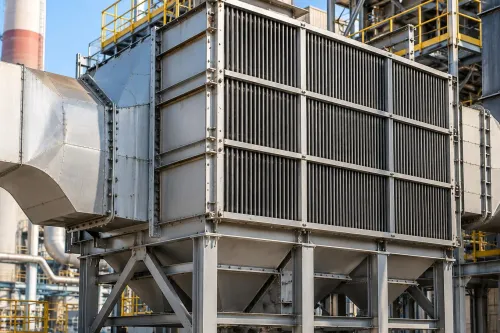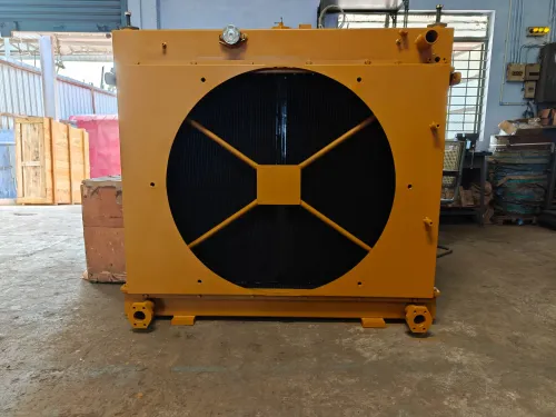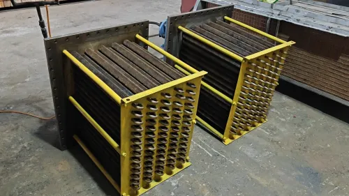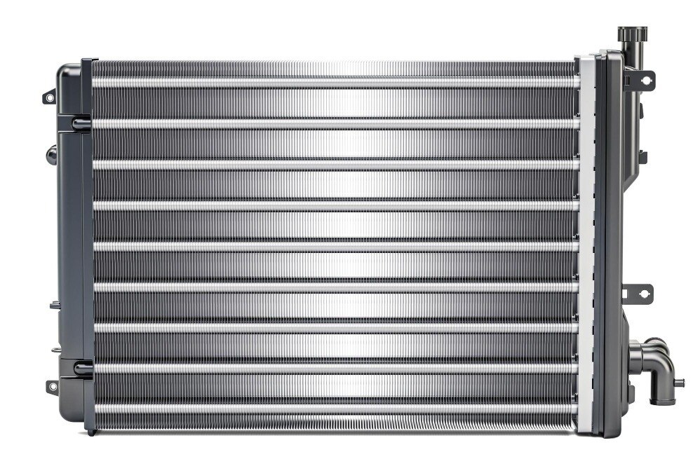
A compact heat exchanger saves space only when its core, airflow, pressure drop, and maintenance plan match the process. By the end, you will be able to compare plate-fin construction with competing designs, test a supplier selection, and identify the operating data required before ordering.
Key takeaways
- Choose the core from heat duty, flow rates, temperatures, and pressure drop.
- Use plate-fin construction when compactness and multiple fluid streams matter.
- Demand thermal, hydraulic, material, and operating data in the selection.
- Protect brazed cores from corrosion, contamination, vibration, and excessive pressure.
What an aluminum plate-fin core contains—and why it is so compact
An aluminum plate-fin heat exchanger builds high area density into a compact core. Alternating parting sheets and corrugated fins create separate air or fluid passages, while side bars and headers, plus end plates, enclose the block. Vacuum brazing joins these layers into a rigid, low-leakage assembly; mechanical joining is another option.
Headers and distributors feed two or more streams without mixing them. One brazed block can combine recuperation, interstage cooling, and stream separation, including three or more independent passages. Aluminum’s low density and high thermal conductivity let thin sheets and fins transfer heat with little material, reducing weight for packaged, mobile, low-temperature, and cryogenic systems.
Fin geometry controls the compromise:
- Plain fins offer lower friction and better fouling tolerance.
- Offset-strip and serrated fins interrupt boundary layers, raising heat transfer and pressure drop.
- Louvered and perforated fins create further interruption, increasing both performance and friction.
Compared with unfinned shell-and-tube tubes, conventional cooling coils, and finned-tube coils, these passages provide far more wetted surface per unit volume. The price is narrow flow paths: pressure drop, fouling, maldistribution, and difficult internal access become more serious.
| Option | Area density | Main consequence |
|---|---|---|
| Shell-and-tube | Lower | Larger, easier-to-clean passages |
| Cooling coil | Moderate | Simple face, less compact |
| Finned-tube coil | Higher air-side area | More volume than a brazed block |
| Plate-fin core | Very high | Minimum volume, maximum sensitivity to blockage and flow imbalance |
When plate-fin construction beats shell-and-tube, gasketed plate, or finned-tube designs
Choose by pressure, fluid cleanliness, access, and corrosion risk—not by compactness alone. Plate-fin construction wins when several streams need close temperature approaches in one lightweight brazed block and the fluids can be filtered, controlled, and kept within the qualified core rating.
| Option | Main advantage | Choose it when |
|---|---|---|
| Plate-fin | Highest area density and low weight | Clean gas or liquid streams, multi-stream recuperation, low-temperature or cryogenic duty |
| Shell-and-tube exchanger | Larger passages and robust pressure capability | High-pressure service, demanding liquid duty, or tube-side mechanical cleaning |
| Gasketed plate heat exchanger | Opens for inspection and gasket replacement | Clean liquid-to-liquid service where internal access matters |
| Finned-tube coil | Wide passages and a simple accessible face | Air-side cooling where tube access and easy coil cleaning outweigh maximum area density |
Aluminum is attractive because low density reduces installed weight, high thermal conductivity supports thin fins and sheets, and vacuum-brazed fabrication creates a rigid core without gaskets between every passage.
That advantage does not prevent aluminum corrosion: chloride-bearing water, unsuitable chemistry, stagnant wet zones, and galvanic contact with steel or copper can cause pitting or crevice damage.
Reject plate-fin construction when you have:
- Pressure above the qualified core rating, excessive temperature, or no suitable relief protection.
- Severely corrosive fluids or dirty streams that cannot be filtered.
- Frequent mechanical cleaning or a need for easy internal access; a brazed core is not normally field-openable.
For a multi-stream block, define the pressure hierarchy, relief devices, and the consequence of cross-contamination before approval. A leak between a high-pressure toxic stream and a low-pressure utility stream is a containment problem, not merely a performance loss.
How to select the core from process data instead of physical dimensions
Start with heat duty in kW, not the available box size. A core with more heat-transfer area is not automatically a larger-capacity cooler: airflow, liquid flow, fouling, approach temperature, and pressure drop decide whether it delivers the duty.
- Record hot-side and cold-side inlet and outlet temperatures, mass or volumetric flow, fluid composition, viscosity, phase-change details, allowable pressure drop on each side, design pressure, design temperature, and altitude.
- Add the available length, width, and height envelope; connection sizes and orientation; insulation thickness; support points; vibration exposure; and maintenance clearances.
- For air, check face velocity, fan power, fin spacing, dust loading, and altitude together. Narrow fin spacing can provide area but plug quickly in dusty air, raising pressure drop and reducing flow.
- For liquids, check channel velocity, viscosity, pump power, particulate-plugging risk, and refrigerant distribution. Unequal refrigerant flow can leave part of the core underfed while the rest carries excessive pressure loss.
- Test the thermal limit with the proposed flow arrangement. Counterflow or cross-counterflow can produce a close approach, but heat-capacity ratios, longitudinal conduction, header losses, flow maldistribution, and permitted pressure drop set the achievable temperature difference.
Use the physical envelope only after the process data define the required geometry. Selecting by core length, width, or height alone can produce a compact exchanger that meets a catalogue area figure yet misses the duty, overloads the fan or pump, or fouls before it reaches stable operation.
What a credible performance selection must show
A credible supplier performance selection fits on one page and ties thermal duty to hydraulic cost. Require a schedule showing:
- Required duty; hot-side and cold-side inlet and outlet temperatures; both flow rates; both pressure drops; approach temperature; altitude and altitude correction; fluid composition, density, viscosity, and specific heat.
- Fin type; fin density; fouling assumptions; design pressure and temperature; and the selected core geometry.
Clean basis | Fouled basis Thermal result | New-core performance | End-of-run performance Pressure drop | Lower resistance | Higher resistance Operating trade-off | Fan or pump power at clean condition | Fan or pump power at fouled condition
Ask which basis controls the selection. A narrow passage that meets duty only when clean can lose capacity after dust or particulate loading.
Equal passage flow in a calculation does not prove equal passage flow in the built core. Request the header, nozzle, and turning-region analysis, plus distributor testing or measured flow evidence; flow maldistribution can leave some passages underused while overloading others.
Require proof that the geometry meets its pressure rating and temperature limit for the specified aluminum alloy, brazing sheet, joint design, and qualification basis. Check thermal expansion at connections, especially where aluminum joins steel or copper piping, because restraint can load the core.
Finally, compare the installed envelope, not the bare core. Add external headers, filters, supports, vibration protection, insulation, and access space; the lightest core can become the largest installed package.
How to protect a brazed core and verify the delivered design
A compact core becomes a failure point when nobody owns filtration, water chemistry, access, or acceptance records. Assign those controls in the purchase specification, not after installation.
1. Install a strainer or filter upstream of every narrow passage and provide a differential-pressure indication. Match water treatment to measured chloride and hardness levels; define fluid-cleanliness limits, freeze protection, and galvanic isolation between aluminum, steel, copper, and stagnant wet zones.
2. Reserve clearance and time to remove filters, inspect headers and nozzles, clean accessible surfaces, and drain and vent the unit. A brazed core is not normally field-openable like a gasketed exchanger, so decide in advance whether fouling or leakage means specialized repair, plugging, or complete replacement.
3. Require drawings that identify passages, headers, nozzles, supports, drains, vents, and maintenance access. Obtain material specifications naming the aluminum alloys and brazing sheet, design pressure and temperature, pressure-test records, leak-test method, vacuum-integrity results where relevant, and the final performance document.
4. Specify brazing quality controls and leak testing before delivery. Where streams cannot tolerate cross-contamination, require helium or another high-sensitivity method, define the pressure hierarchy, set relief protection, and state the allowable consequence of leakage between streams.
Premier Engineering Works can use these process limits, envelope dimensions, and records to develop a core design around the duty, including thermal expansion at dissimilar-metal connections, rather than selecting by catalogue dimensions alone.
Frequently asked questions
Why is an aluminum plate-fin heat exchanger so compact?
Alternating parting sheets and corrugated fins create separate passages with high heat-transfer area inside a small brazed core. Side bars, headers, and end plates enclose the passages.
When does plate-fin construction beat shell-and-tube or gasketed plate designs?
It suits applications that need high area density, low weight, multiple streams, or close temperature approaches. Shell-and-tube is easier to inspect and repair, while gasketed plate exchangers offer convenient opening and cleaning.
How should you select a plate-fin core?
Start with process duty, inlet and outlet temperatures, mass flow, fluid properties, allowable pressure drop, operating pressure, fouling risk, and material compatibility—not the available physical space alone.
What should a credible performance selection show?
Request heat duty, outlet temperatures, flow rates, pressure drops for each stream, design pressures and temperatures, fluid properties, fouling assumptions, materials, and the calculation basis.
How do you protect and verify a brazed aluminum core?
Control corrosion and contamination, prevent vibration and unsupported piping loads, stay within pressure and temperature limits, and check the delivered unit against drawings, nameplates, test records, and the approved selection.