A process that needs hot, clean, stable air faces a choice between steam, direct firing, electric resistance, water, and a liquid heat-transfer circuit. By the end, you will know how a thermic fluid radiator transfers heat, how its controls and safeguards work, and what operating data is needed to size one without damaging the fluid or sacrificing air-temperature uniformity.
Key takeaways
- Use finned tubes to transfer heat from circulating oil into the air stream.
- Choose thermic fluid when stable high temperatures and indirect heating matter.
- Include a pump, expansion tank, heater, controls, filters and safety devices.
- Size the radiator from airflow, inlet and outlet temperatures, and heat loss.
How a thermic fluid radiator heats an air stream
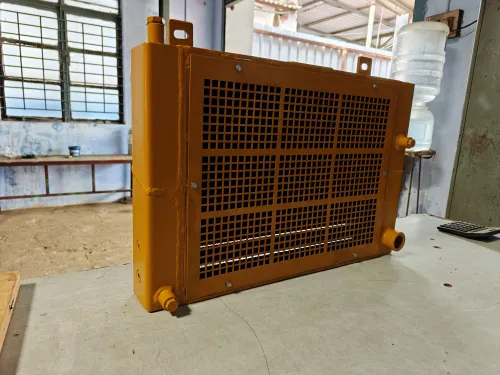
A thermic fluid radiator is a liquid-to-air heat exchanger: hot heat-transfer oil flows through tubes while process air passes over the outside surfaces. The same assembly may be called a thermal oil air heater or a finned-tube radiator coil.
1. A circulation pump sends heated thermic fluid into the coil headers and tubes. The oil stays in a closed circuit; it does not mix with the air or boil inside the radiator.
2. Heat moves through the tube wall by conduction, then spreads through aluminium or steel fins attached to the tubes. These fins enlarge the contact area, allowing moving air to absorb heat through liquid-to-air heat transfer.
3. An air-handling fan pushes process air across the finned face. Its outlet temperature depends on oil temperature and flow, air mass flow, coil surface area, and how evenly air reaches the coil.
4. The warmed air leaves the coil for a dryer, oven, or process duct, while cooler oil returns to the heater for reheating.
This indirect arrangement keeps combustion gases out of the product airstream. It also adds pumping power, thermal losses, and a potential leak point, so clean coil surfaces, correct fluid flow, and even air distribution matter. A high average outlet temperature cannot correct cold or overheated bands caused by poor airflow distribution.
Why use thermic fluid instead of steam, direct firing, or electric heat?
The choice turns on separation and temperature control. A thermic fluid circuit suits controlled high-temperature air heating when you need stable, adjustable air temperatures above hot-water limits without building a high-pressure steam and condensate system. It also keeps the heater separate from the airstream, which matters when combustion gases cannot contact the product.
| Option | Main advantage | Cost or limitation |
|---|---|---|
| Thermic fluid | Indirect heating at high temperature with a remote heater | Adds pumping power, fluid losses, leak risk, and circuit maintenance |
| Steam | High heat-transfer capacity and familiar equipment | Requires steam pressure, traps, condensate return, and freeze protection |
| Direct-fired air heater | Transfers combustion heat directly with few heat-transfer steps | Combustion products enter the process air unless a separate exhaust arrangement prevents it |
| Electric resistance heating | Simple, clean, and easy to control at small capacity | Needs substantial electrical capacity and becomes costly at high duty |
A steam radiator comparison favours thermic fluid when condensate infrastructure is burdensome. A direct-fired air heater can deliver heat efficiently, but it is unsuitable for air that must remain free of combustion products.
Electric resistance heating can be simpler for a small unit; a shared fluid loop becomes more attractive when several air users draw heat from one central source.
Thermic fluid is not automatically more efficient. Pump power, heater stack losses, coil temperature difference, insulation, and exhaust-heat recovery determine the result. Maintain the manufacturer’s minimum fluid flow: throttling a high-duty heater too far can raise film temperature above the measured bulk temperature and degrade the fluid.
What the complete heating circuit must include
A complete circuit moves thermal fluid from the expansion tank connection through the thermic fluid circulation pump, thermal fluid heater, and radiator before returning to the heater. The radiator transfers heat to air moved by the supply fan, while sensors and interlocks prevent heating when flow or airflow is missing.
- Connect the expansion tank to the low-pressure side of the circuit, with a cold seal, vent arrangement, and sufficient elevation. This provides room for fluid expansion and prevents the pump from drawing vapour during heat-up.
- Install the thermic fluid circulation pump with strainers, isolation valves, and a flow switch. Low flow must stop firing because stagnant fluid can overheat against the heater surface.
- Fit the thermal fluid heater with a high-temperature limit, burner or electrical cut-out, relief protection, and controls for safe start-up and shutdown.
- Place the radiator in the air duct and measure both fluid and air temperatures. A control valve or bypass line adjusts heat delivery without stopping circulation through the heater.
- Interlock the air-handling fan with the heater. The air-handling fan interlock must prevent firing until airflow is proven and shut the heater down if the fan trips.
- Provide drain points, isolation valves, leak containment, and a defined method for removing degraded fluid. Protect people from hot surfaces and route expansion-tank vents away from ignition sources.
The system must remain filled during cooldown as well as operation. A relief device does not replace low-flow protection, and a low-pressure circuit still carries combustible-fluid and hot-surface hazards.
How to control air temperature without overheating the fluid
Regulate outlet-air temperature by changing heat input or air mixing, not by starving a fired heater of circulation. A three-way control valve can divert hot fluid through a fluid bypass line while preserving the heater’s specified minimum flow. Flow modulation with a variable-speed pump works only when circulation remains above that limit.
| Method | Outlet-air control | Fluid protection |
|---|---|---|
| Three-way control valve | Diverts part of the hot fluid around the radiator | Maintains heater flow and reduces radiator duty without creating a low-flow heater condition |
| Burner modulation | Matches heater output to air-temperature demand | Limits heat input, but still requires proven circulation and a high film-temperature limit |
| Air bypass damper | Mixes heated air with unheated air downstream | Protects the fluid because radiator duty stays available, though poor mixing creates hot and cold air bands |
| Coil or fan flow modulation | Changes air-side heat pickup | Requires minimum fluid flow; excessive face velocity or uneven distribution can produce local coil hot spots |
Install a flow switch or differential-pressure transmitter that shuts the burner when circulation falls below the heater maker’s minimum. Add high-temperature protection based on fluid outlet or heater temperature, while recognising that fluid film temperature can exceed the measured bulk temperature.
Keep the expansion tank from continuous hot-air contact, and investigate fouling, blocked passages, or burner imbalance when fluid analysis shows oxidation or viscosity increase.
How to size and specify the radiator for your process
Size the radiator from the heat duty and the air-side constraint, not from the desired fluid temperature alone. An undersized face raises velocity and air-side pressure drop; an oversized or poorly distributed coil leaves cold and hot bands across the outlet.
1. State the process duty: product or material being heated, required heating rate, operating hours, moisture load, contaminants, fouling risk, and whether the air is fresh, recirculated, or mixed. Provide air inlet and outlet temperature, target temperature uniformity, and allowable warm-up time.
2. Provide air volume in m³/h at the actual inlet temperature and pressure, plus duct dimensions and fan capacity. Identify the maximum acceptable air-side pressure drop and available static pressure; these determine face area, tube rows, fin spacing, and fan selection.
3. Specify the fluid: thermal-oil name, allowable bulk and maximum film temperature, fluid supply and return temperature, design flow rate, viscosity at operating temperature, and permitted pressure drop. The coil must tolerate the fluid’s chemistry and heater limits, not merely the outlet-air temperature.
4. Confirm construction requirements: tube and header material, fin material, corrosion exposure, design pressure, design temperature, weld or brazing requirements, drainability, and cleaning access. Copper and aluminium choices need review when the fluid, air contaminants, or wash-down chemicals could attack them.
5. Give installation details: horizontal or vertical orientation, duct connection size, airflow straightening, mixing length, bypass arrangement, sensor locations, maintenance clearance, supports, insulation, and thermal expansion movement. Premier Engineering Works can use these inputs to distinguish a radiator brief from a generic coil request.
Frequently asked questions
How does a thermic fluid radiator heat an air stream?
Hot heat-transfer oil flows through finned tubes while process air passes over the external fins, transferring heat without direct contact.
Why use thermic fluid instead of steam, direct firing or electric heat?
Thermic fluid provides indirect, stable high-temperature heating with low system pressure and avoids combustion products in the air stream.
What equipment belongs in a complete thermic fluid heating circuit?
The circuit needs a heater, circulation pump, expansion tank, insulated piping, valves, temperature instruments, filtration and protection against low flow, overtemperature and leaks.
How do you control air temperature without overheating the thermic fluid?
Use air outlet temperature feedback to regulate fluid flow or heater duty, while independent high-temperature and low-flow trips protect the oil.
What information is needed to size a thermic fluid radiator?
Provide airflow, air inlet and outlet temperatures, operating altitude, allowable pressure drop, fluid temperature, fouling conditions and heat-load details.