Uneven drying usually starts with more than a temperature-setting problem: steam pressure, condensate drainage, airflow, humidity, and product loading all affect the heat reaching the material. You will be able to trace the steam and condensate path, estimate the coil duty, specify operating conditions, and commission the air side for uniform outlet temperature.
Key takeaways
- Match coil capacity to airflow, moisture load, and steam pressure.
- Route condensate downward and remove non-condensable air at startup.
- Use traps, vacuum breakers, and freeze protection to prevent coil damage.
- Measure leaving-air temperatures across the coil during commissioning.
How Condensing Steam Turns a Coil into a Stable Heating Surface
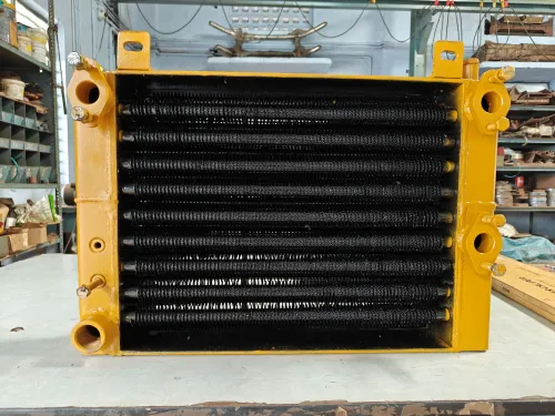
Steam enters the coil’s tubes and condenses against their inner surfaces. As it changes from vapour to liquid, it releases latent heat through the tube wall and into the fins. The fins spread that heat across a larger air-contact area, so moving process air warms as it crosses the coil.
The heating surface stays comparatively steady because condensing steam remains near its saturation temperature while pressure remains steady. Saturated steam at approximately 0 psig condenses at 212°F (100°C); at 100 psig, it condenses at about 338°F (170°C). Steam pressure sets the available surface temperature, not steam mass-flow rate alone.
Direct-fired air heaters add energy through a flame and combustion gases, while electric resistance heaters add energy as current passes through elements. Their local surfaces can cycle sharply with burner firing or electrical modulation. A steam radiator coil distributes a broad, nearly uniform surface temperature, reducing hot spots that can overdry or scorch material.
Do not treat normal inlet pressure as proof of stable heating. Air trapped inside the coil creates a cold diffusion layer, and retained condensate covers active surface, slows response, and lowers output. Keep air venting effective and condensate draining continuously; otherwise, a good pressure reading can coexist with uneven drying.
Choose Coil Capacity from Airflow, Moisture Load, and Steam Conditions
Calculate coil capacity from the air and product duty, not from steam pressure alone. Use airflow and the required inlet and outlet air temperature to find sensible heat:
Q sensible = air mass flow × air specific heat × (outlet temperature − inlet temperature).
Add the energy needed to evaporate the target moisture removal. The humidity load, product feed rate, initial moisture, residence time, and required drying rate determine this latent duty.
Size for the combined sensible and latent load, then correct the catalog rating for face velocity, altitude, fouled fins, bypass leakage, entering-air humidity, minimum steam pressure, and condensate backpressure.
| Quantity | What it controls | What to verify |
|---|---|---|
| Steam pressure | Saturation temperature at the tube wall and available heat-transfer driving force | Pressure at the coil inlet and the minimum pressure while the valve is open |
| Leaving-air temperature | Air condition delivered to the dryer | Temperature after the coil at the actual airflow and load |
| Steam mass flow | How much energy the coil supplies over time | Valve capacity, condensate discharge, and control range |
At about 0 psig, saturated steam condenses near 212°F (100°C); at 100 psig, it condenses near 338°F (170°C). That pressure does not equal the air temperature leaving the coil. Changing airflow changes the outlet temperature at the same pressure, while a pressure-reducing valve sets a maximum coil temperature rather than guaranteeing drying uniformity.
Confirm performance at minimum steam pressure and design airflow. A tightly controlled outlet temperature still produces variable drying if exhaust humidity, recirculation, product loading, or feed moisture changes.
Build the Steam, Condensate, and Air-Removal Flow Path Correctly
A reliable path is: isolation valve, strainer, steam separator, inlet control valve, coil, steam trap, check valve, and condensate return. Put a drip leg and trap on the steam main where the distribution layout creates a low point.
The separator removes liquid water before it reaches the coil; the strainer protects the control valve and trap.
Use a float-and-thermostatic steam trap at the coil outlet when continuous drainage and startup air venting matter. Size it at the minimum operating differential pressure, not only at maximum heating duty. Include the control-valve pressure drop, condensate-return elevation, separator or flash-steam effects, and return-line backpressure. A trap that passes full-load condensate can stall during startup.
Install the vacuum breaker on the coil steam side, close enough to admit air when the control valve shuts. Route the condensate line continuously downward to the trap and return header; avoid pockets and lifted sections. Fit the check valve after the trap to stop return water or steam from flowing backward into the coil.
| Operating condition | Main drainage risk | Design response |
|---|---|---|
| Low load | The modulating valve lowers coil pressure below return pressure, flooding the coil | Preserve minimum differential pressure, use a vacuum breaker, and verify trap capacity at turndown |
| High load | Condensate volume exceeds trap capacity, causing water hammer and cold areas | Check maximum flow, provide adequate pipe size, and keep the return line free-draining |
| Shutdown | Trapped condensate freezes or creates vacuum | Cut steam promptly, maintain required airflow protection, open the vacuum breaker, and fully drain the coil |
Prevent Flooding, Water Hammer, Fouling, and Freeze Damage
A coil with normal inlet steam pressure can still deliver cold, patchy air. The usual causes are trapped condensate, non-condensable air, wet steam, or restricted airflow across the face.
Match each symptom to a physical check:
- A cold top section with a warm bottom section points to non-condensable air. Check the vent path and confirm that the air vent discharges during startup; repair blocked vents or poor air removal.
- Gurgling, pipe movement, or a sharp banging noise indicates water hammer. Inspect for standing condensate, sagging return lines, improper lifts, and a failed trap. Restore continuous drainage toward the trap and replace the trap if it cannot discharge at the operating load.
- A coil that stays flooded at low output has insufficient trap differential pressure or an unsuitable trap. Verify the minimum steam pressure against condensate-return pressure, then correct the control-valve range or install a float-and-thermostatic trap sized for continuous discharge.
- Uneven air temperature with rising fan pressure indicates fouling and fin damage. Clean dust from the fins, straighten crushed fins with a fin comb, and seal bypass gaps around the frame.
- Water droplets entering the coil signal wet steam or poor separation. Check the upstream separator, strainer, and drip leg; remove accumulated water before it reaches the coil.
- A shutdown coil exposed to freezing air needs prompt drainage. Close the steam valve, open the vacuum breaker, and drain condensate; add freeze protection or airflow interlocking if cold outdoor air can pass over the coil.
Commission a Multi-Row Coil for Uniform Air Temperature
A coil face is balanced by measuring what each section receives and produces, not by trusting the inlet steam gauge. Divide the multi-row coil face into a grid, measure air velocity at each point with a calibrated anemometer, and record dry-bulb temperature before and after the coil.
The resulting temperature mapping exposes stagnant zones, bypass leakage, and hot streaks.
Commission at design airflow and the actual minimum steam pressure, with clean filters and the production fan running. Then:
- Traverse the face for velocity; correct damper position, fan speed, or duct transitions until no section carries disproportionate flow.
- Measure entering and leaving air temperature at the same grid points; compare average rise and temperature spread across the face.
- Record steam inlet pressure, coil differential pressure, condensate temperature, and trap discharge while the control valve modulates.
- Check fin cleanliness, tube-row condition, casing seals, and the air vent; trapped non-condensable gas creates a cold region despite normal pressure.
Ask the manufacturer for a performance schedule tied to your entering-air temperature, humidity, airflow, altitude, steam pressure, minimum steam pressure, and condensate-return pressure. Request these figures:
| Parameter | Information to request |
|---|---|
| Capacity | Rated heat output at stated conditions |
| Air side | Face velocity, airflow range, and pressure drop |
| Steam side | Steam consumption, operating pressure range, and minimum draining pressure |
| Uniformity | Maximum temperature variation across the face |
| Construction | Row arrangement, fin spacing, circuiting, and test method |
When Premier Engineering Works quotes a custom coil, require the drawing and test record to show how the coil was built, tested, and balanced.
Related product
 | Steam Radiator Manufacturer In Coimbatore Steam Radiator Manufacturer In Coimbatore | Premier Engineering Works View product → |
Frequently asked questions
How does condensing steam create a stable heating surface?
Steam condenses inside the tubes and releases latent heat through the tube wall. Fins distribute that heat across the air-contact surface as process air passes over the coil.
What determines the required steam coil capacity?
Size the coil from airflow, moisture load, entering and target leaving-air temperatures, steam pressure, condensate conditions, and the required heat-transfer duty.
How should steam and condensate flow through an industrial coil?
Provide a clear steam inlet, a low-point condensate outlet, a correctly selected steam trap, and an air-removal path for non-condensable gases during startup.
How do you prevent water hammer, fouling, and freeze damage?
Drain condensate continuously, avoid lifting condensate without proper pressure differential, remove air, keep heat-transfer surfaces clean, and protect the coil when cold air can enter.
How do you commission a multi-row steam coil for uniform air temperature?
Check steam pressure and condensate drainage, then measure air temperatures at multiple points downstream and correct airflow distribution, dampers, or coil conditions when readings vary.