Air is a difficult fluid to heat efficiently: its low density and thermal conductivity make the air side of a coil the usual bottleneck. You will learn how fins reduce that resistance, calculate the required heat duty, and choose a coil geometry that balances capacity, pressure drop, fouling, and serviceability.
Key takeaways
- Fins expand air-side area, reducing the resistance that limits heat transfer.
- Calculate heat duty from airflow, air temperatures, and air heat capacity.
- Choose fin spacing and tube geometry to control capacity, pressure drop, and fouling.
- Compare coil output with fan power before finalising the design.
Why fins improve air heating more than a plain tube
Fins improve air heating by multiplying the effective heat-transfer area exposed to the air. That matters because air-side heat transfer resistance usually controls the coil: air conducts heat poorly compared with water, steam condensate, or thermal oil.
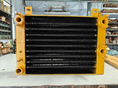
A finned tube heat exchanger gives the air more surface to contact without requiring a proportional increase in tube length.
The fin does not inherently raise the local air-film heat-transfer coefficient. It spreads heat from the tube wall across a larger surface, so the calculation must apply overall surface efficiency, ηo; fin tips are cooler than the tube base. If you count every square metre at tube temperature, you will overstate capacity.
| Design | Surface available at the same tube length | Result |
|---|---|---|
| Plain tube comparison | Small outside area | Larger coil or more rows for the same air-heating duty |
| Finned tube | Tube area plus bonded fin area | Higher heat output from a compact coil |
| Over-finned tube | More area but lower fin efficiency and higher resistance | Diminishing capacity gain with added material |
Fins reduce required coil size, not the airflow needed for a specified air mass flow and temperature rise. The gain also has a limit: once air-side resistance falls, tube-wall, tube-side, and fouling resistances occupy more of the total.
More rows can then add capacity, but each row also increases air pressure drop, so choose fin area and row count against fan capacity and allowable pressure loss.
How heat moves from the heating medium into the air
Heat crosses from the heating fluid to the air in a chain: through the fluid film, across the tube wall, through the fin-to-tube contact, and across the air film. The heating medium enters hotter than the air, loses enthalpy along the circuit, and leaves cooler.
Air gains that same heat as it passes successive tube rows.
The driving force is the temperature difference between the medium and the local air, not simply the inlet-medium temperature. Coil output follows Q = U A ΔTlm, where U includes fluid films, tube-wall conduction, fin contact, and fouling.
The air-side film usually supplies the largest resistance; poor fin bonding adds contact resistance and leaves nominal fin area ineffective.
| Heating arrangement | Medium temperature behaviour | Effect on air heating |
|---|---|---|
| Hot water heating coil | Water cools continuously through the tubes | Output depends on the mean water-to-air temperature difference |
| Steam air heater | Condensing steam stays near its saturation temperature | Large temperature difference remains until condensate drainage or non-condensable gas interferes |
| Thermal oil coil | Oil cools along the circuit; viscosity affects internal resistance | Tube-side flow distribution influences the leaving-air temperature |
| Refrigerant coil heating airfeed | Refrigerant evaporates near its saturation temperature | Pressure and refrigerant distribution set the available heating temperature |
Higher tube-side velocity improves internal convection and reduces temperature stratification, but increases pumping power and erosion risk. Higher air velocity improves the air coefficient while increasing pressure drop; extra rows reduce the air-temperature approach, with diminishing gain as air-side resistance and fan cost accumulate.
How to calculate heat duty and turn it into coil dimensions
Start with required duty, not tube count: Q = m·cp·ΔT. Convert air volume flow to air mass flow using air density at the coil’s mean temperature, then apply the required entering-to-leaving air temperature rise.
1. Calculate the air-side duty and check the leaving temperature. Use mean air properties, or divide the coil into sections, because density and viscosity change as air heats. A large temperature rise can otherwise distort velocity, Reynolds number, and pressure-drop results.
2. Select face area from allowable face velocity and the coil’s free-area ratio. Face area equals air volume flow divided by face velocity; increase it when fan pressure is limited. Control casing leakage, blanked sections, and bypass, or the rated airflow will not cross the fins.
3. Establish heating-medium conditions: water or oil inlet and outlet temperatures and flow, or steam pressure and condensing temperature. Use the resulting mean temperature difference in the heating coil sizing calculation, then solve for required UA with overall surface efficiency, ηo, tube-wall resistance, and fouling resistances included.
4. Add tube rows until the required leaving-air temperature is reached. More rows improve temperature approach, but each added row increases air-side pressure drop with diminishing capacity gains. Check the total drop against the fan allowance.
5. Set fin spacing from fouling risk and pressure drop. Wide spacing suits dusty or lint-heavy air; tighter spacing provides more surface in a shorter coil but loads quickly. Convert the selected row count and fin pitch into coil depth, face width, tube length, and circuiting, then verify tube-side velocity and medium pressure loss.
How to choose fins, tubes, and tube-bank geometry
Choose the fin material and bond before increasing surface area. Aluminium gives high conductivity and low mass for clean, dry air; copper suits compact coils but costs more and needs galvanic protection with dissimilar tubes. Stainless steel or coated steel fits corrosive air, high temperatures, or abrasive service, with a conductivity penalty.
| Option | Selection | Air-stream fit |
|---|---|---|
| Fin form | Plain, widely spaced fins | Dust, lint, washable air, low pressure drop |
| Fin form | Louvered, wavy, or serrated fins | Clean air where mixing and compact size justify higher pressure drop |
| Construction | L fins, embedded fins, mechanically bonded fins, or extruded fins | Select the joint that resists thermal cycling, corrosion, and vibration; loose contact wastes nominal fin area |
| Tube material | Copper, carbon steel, or stainless steel | Match water, steam, thermal oil, or refrigerant chemistry and design temperature |
| Tube geometry | Smaller diameter, staggered rows | Higher heat transfer and compactness, but greater resistance |
| Tube geometry | Larger diameter, inline rows | Lower pressure drop, easier cleaning, and better tolerance of dirty air |
Use 0.5–1.5 mm aluminium fins as a starting range, then set fin spacing from dust loading and cleaning access rather than area alone. Tight spacing traps lint. Keep the fin path short; a long, thin fin loses efficiency even when its geometric area looks impressive.
Rate the bank using velocity through its minimum free-flow area, not face velocity. Control casing bypass and blanked sections. Premier Engineering Works can use the air chemistry, medium, temperature, allowable pressure drop, and heating coil construction to compare these choices rather than treating every finned bank as equivalent.
Related products
 | L Fin Heat Exchanger Manufacturer L Fin Heat Exchanger Manufacturer | Premier Engineering Works View product → |
 | Finned Tube Bundle Finned Tube Bundle Manufacturer In Coimbatore | Premier Engineering Works View product → |
How to balance capacity against fan power, fouling, and operating life
1. Set the air velocity from the duty and the available fan budget, not from heat-transfer coefficient alone. Higher velocity raises the air-side coefficient and can reduce required coil face area, but fan power rises with airflow multiplied by pressure drop and divided by fan efficiency.
A compact coil can therefore cost more to operate than a larger, less restrictive coil.
2. Tighten fin spacing only when the air is clean and filtration is reliable. Closely spaced fins add surface area, but dust, fibers, and oily aerosols quickly bridge narrow passages. Air-side fouling then reduces open area, increases local velocity and pressure drop, and adds thermal contact resistance.
Provide cleaning access and select fin spacing for the actual contaminant load.
3. Keep the coil surface above the entering-air dew point when the heater is intended for sensible heating. A cold patch creates condensate that wets dust, promotes corrosion, adds latent demand, and can raise pressure drop. If condensation is unavoidable, specify drainage, corrosion-resistant materials, and a fin spacing that will not trap moisture.
4. Compare coils only at matching airflow, temperatures, humidity, heating-fluid flow, altitude, cleanliness, and pressure-drop measurement points. Use an AHRI Standard 410 coil rating as a reference, then check tube-side pressure drop and pumping power; extra tube velocity or rows can improve transfer, but erosion, diminishing row gains, and rising resistance shorten the practical advantage.
Frequently asked questions
Why do fins improve air heating more than a plain tube?
Fins multiply the air-contact area, helping overcome air’s relatively high thermal resistance compared with water, steam, or thermal oil.
How do you calculate heat duty for an air-heating coil?
Use airflow, air density, specific heat, and the required air-temperature rise: Q = ṁ × cp × ΔT.
How do you turn heat duty into finned tube coil dimensions?
Select the heating-medium temperatures and target overall heat-transfer coefficient, then estimate required surface area and define tube rows, fin area, face area, and coil depth.
How should you balance heating capacity against fan power and fouling?
Compare the coil’s heat output with its air-side pressure drop, then select fin spacing and tube-bank geometry that suit dust loading, cleaning access, and operating life.
Related product
 | Cooling Equipment Premier Engineering Works specialises in designing and manufacturing customised cooling coils to meet the precise requirements of your application. View product → |