High-pressure heat transfer depends on more than the exchanger’s stated capacity: each fluid circuit needs its own pressure boundary, temperature limit, flow path, and inspection record. By the end, you will know how heat moves through the exchanger, how engineers select its arrangement, and which design and manufacturing documents to demand before purchase.
Key takeaways
- Keep process fluids separate with a metal tube wall.
- Rate the shell side and tube side as separate pressure boundaries.
- Use baffles and expansion features to manage flow and thermal stress.
- Request design calculations, material records, and pressure-test certificates.
How heat crosses the exchanger without mixing the fluids
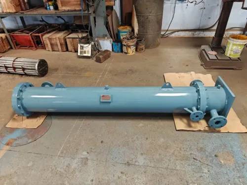
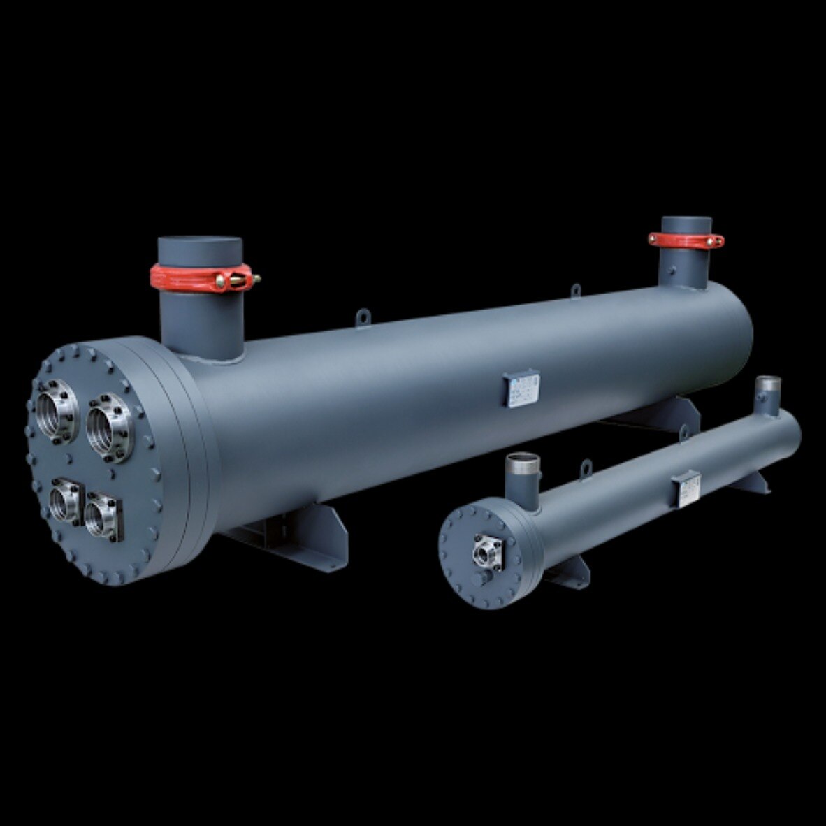
A shell-and-tube heat exchanger keeps two process circuits physically separate while allowing heat to cross a thin metal wall. The hotter stream may run through the tube side; the colder stream fills the shell side around the tubes, although the assignment can be reversed.
1. The hot fluid transfers heat through its tube-side film, across the tube wall, and through the shell-side film into the cold fluid. Fouling or low velocity thickens these films and reduces heat duty.
2. Tubesheets hold the tubes and divide the shell-side space from the channel heads. Tube-to-tubesheet joints—rolled, welded, or seal-welded and expanded—form leak-tight pressure-boundary details; a failed joint can let one process stream enter the other.
3. Channel heads and covers direct tube-side flow into and out of the passes. The shell contains shell-side pressure, nozzles connect the exchanger to plant piping, and gaskets seal removable flanges and covers.
4. Baffles force shell-side flow across, rather than straight along, the tubes. This cross-flow increases turbulence and heat transfer and supports tubes against vibration, but it also creates a pressure-drop penalty.
5. An expansion joint can absorb shell-to-tube thermal movement in a fixed-tubesheet design, but it becomes another fatigue-sensitive pressure-boundary component.
6. Keep the circuits isolated even when one operates at much higher pressure. A tube leak can drive the high-pressure fluid into the low-pressure stream, contaminating product and creating an overpressure hazard.
Why one exchanger needs two pressure and temperature ratings
A single pressure rating is inadequate because the tube circuit and shell circuit impose different loads on different parts. Specify tube-side and shell-side operating pressure, design pressure, design temperature, test pressure, vacuum requirement, and allowable differential pressure across the tube wall.
- Read operating pressure as the normal pressure at the stated flow and temperature. Design pressure is the pressure selected for the credible maximum, and design temperature is the metal-temperature limit used for stress and materials. State both sets separately for the tube side and shell side.
- Check each pressure boundary: channel heads, tubesheets, tubes, shell, heads, nozzles, flanges, and tube-to-tubesheet joints. A tube rupture can expose the low-pressure side to the high-pressure side, while a blocked-in liquid can overpressure a circuit through thermal expansion.
- Define whether each circuit must withstand full vacuum or only a specified partial vacuum. A hydrostatic test uses liquid; a pneumatic test uses gas and stores far more hazardous energy. Record test pressure and the code-required limits rather than treating either test as an operating rating.
- Designers often place higher pressure in the smaller-diameter tube circuit because shell wall requirements rise with diameter. Choose shell-side high pressure instead when corrosion allowance, cleanability, velocity, pressure drop, phase change, or design temperature makes that arrangement safer or more practical.
- Set relief-device pressure and capacity for blocked outlets, trapped liquid expansion, fire exposure, and tube rupture. Normal-flow relief sizing does not cover every overpressure case. Include the tube wall’s allowable differential pressure in the final specification.
How baffles, expansion features, and joints control high-pressure service
Baffles force shell-side cross-flow across tubes, raising turbulence and heat transfer while supporting tubes against tube vibration; the cost is pressure drop. Closer spacing improves transfer but increases pressure loss, while wider spacing lowers loss and lengthens unsupported tube spans.
Baffle cut, leakage paths, and bypass streams determine whether nominal shell-side velocity represents the active flow.
Vibration review must distinguish vortex shedding, turbulent buffeting, acoustic excitation, and fluid-elastic instability. The last can damage tubes rapidly when velocity and bundle geometry enter an unstable region, so check tube span, support clearance, flow distribution, and fluid density—not natural frequency alone. Higher velocity also increases erosion, pressure loss, and pumping power.
| Arrangement | Thermal-movement response | Pressure-boundary trade-off |
|---|---|---|
| Fixed-tubesheet | Shell and tubes remain restrained together | Differential expansion creates axial loads in tubes, tubesheets, and joints |
| U-tube | Tube legs flex as temperature changes | Bend geometry complicates cleaning and tube replacement |
| Floating-head | Tube bundle moves relative to the shell | More seals and joints require leak checks |
| Shell-side expansion joint | Bellows absorb shell-to-tube expansion | Fatigue, corrosion, vibration, and nozzle-load checks become critical |
A rolled joint offers mechanical grip but needs crevice and cyclic-service review. A strength-welded joint provides pullout resistance; a seal-welded-and-expanded joint combines sealing with mechanical support, while a welded joint suits specified leak-tightness and code requirements. Match the joint to material, pressure, temperature, and service cycles.
Check gaskets and expansion joints as independent pressure boundaries, not accessories.
What inputs determine the exchanger size and operating limit
A kilowatt figure cannot size an exchanger because the same heat duty can require very different area, passes, materials, and pressure limits in different plants.
- Hot and cold inlet and outlet temperatures
- Mass flow rate on each side
- Fluid phase and properties, including density, viscosity, heat capacity, and thermal conductivity
- Heat duty
- Allowable tube-side and shell-side pressure drop
- Fouling resistance
- Material compatibility
- Required operating cycle, including startup, shutdown, cycling, and upset conditions
The thermal design uses the log mean temperature difference, or LMTD. Multipass and crossflow arrangements require an LMTD correction factor under TEMA practice; ignoring it can produce an exchanger that appears large enough but misses its outlet temperature.
Velocity creates a direct trade-off:
| Condition | Thermal effect | Operating consequence |
|---|---|---|
| Low velocity | Lower film coefficient | Less pressure loss, but more fouling and a larger required surface |
| High velocity | Higher film coefficient | More erosion, vibration, pressure loss, and pumping or compression power |
A fouling factor does not guarantee rated duty. Deposits at inlets, dead zones, phase-change interfaces, or low-velocity regions create maldistribution that a uniform allowance cannot represent. Chloride-containing water also demands review of concentration, temperature, oxygenation, crevices, weld condition, and shutdown chemistry because susceptible stainless-steel tubes can suffer chloride stress-corrosion cracking.
Plugging a leaking tube removes area and changes velocity and pressure drop in the remaining tubes. Establish tube-plugging limits in the specification. Generic sizing ends when detailed thermal design, correction factors, maldistribution analysis, vibration review, and plugging limits begin.
Which documents prove the pressure boundary is fit for service
Acceptance starts with the code, not the brochure. Put the exact governing pressure-vessel code, section, edition, certification scope, and jurisdiction in the purchase order, then verify them on the final nameplate and data report. ASME, European, and American references are not interchangeable claims.
API 660 supplements the pressure-vessel code for petroleum and petrochemical exchangers; TEMA addresses construction, nomenclature, tolerances, and recommended practices, but neither replaces that code. Treat Premier Engineering Works as a candidate only when it converts your process data into this traceable, code-aligned design record rather than quoting an unqualified capacity.
- Material certificates must identify grade, heat or lot number, thickness, and traceability for the shell, tubes, tubesheets, heads, nozzles, and weld consumables.
- Request the approved weld procedure and welder qualification records for each relevant process and material combination.
- Match weld maps to production records showing joint numbers, filler metals, heat treatment, and repair history.
- Check non-destructive examination reports for method, extent, indications, disposition, and acceptance criteria.
- Require tube-to-tubesheet inspection and leak-test records, including the joint type: rolled, seal-welded, strength-welded, or welded.
- The hydrostatic test or pneumatic test record must state medium, pressure, hold time, test temperature, and acceptance criteria.
- Obtain relief-device set pressure and sizing basis, vacuum design confirmation, and the final nameplate and data report showing separate shell-side and tube-side design limits.
| Reference | Proves | Does not replace |
|---|---|---|
| Pressure-vessel code | Boundary design and certification | Exchanger-specific practice |
| API 660 | Petroleum exchanger requirements | The governing code |
| TEMA | Construction and tolerances | Pressure-boundary certification |
Related products
 | Cooling Equipment Our evaporators boast impressive capacities, reaching up to a remarkable 2600 kW. View product → |
 | Cooling Equipment Our condensers boast impressive capacities, reaching up to a remarkable 4700 kW. View product → |
Frequently asked questions
How does heat cross a shell-and-tube exchanger without mixing the fluids?
Heat passes through the tube wall while the tube-side and shell-side fluids remain in separate circuits.
Why does a shell-and-tube exchanger need two pressure and temperature ratings?
The shell side and tube side are separate pressure boundaries, so each requires its own design pressure and design temperature.
How do baffles, expansion features, and joints control high-pressure service?
Baffles support tubes and direct shell-side flow, while expansion features and correctly designed joints manage thermal movement and prevent leakage.
What inputs determine the exchanger size and operating limit?
Sizing depends on heat duty, fluid flow rates, inlet and outlet temperatures, allowable pressure drops, fluid properties, materials, and design pressure and temperature.
Which documents prove the pressure boundary is fit for service?
Review the approved design calculations, material certificates, weld records, non-destructive examination reports, pressure-test certificate, and inspection documentation.
Related product
 | Shell and Tube Condenser Shell and Tube Condenser Manufacturer In Coimbatore | Premier Engineering Works View product → |